Thursday, December 19, 2013

Find and Replace

The examples below are related to using Access's built-in Find and Replace functions.

Select a field and then Ctrl+F to open the Find and Replace Dialog.

Example Find:  Find Nulls (Nulls look like a blank empty fields)

Click on images to view


Example Find and Replace an empty field (empty = blank)


Enter closed quotes "" (double quotes) in Find and Replace empty fields.


To Find and Replace anything (except Nulls) use the asterisk *


Change Multiple Records

To change multiple records unlock the records and select a column in the lower window.

Then select Ctrl+F

Tip:  Filter the records to chose which records are being updated.


Use Find and Replace dialog box to change data - Access - Office.com

Note that Microsoft has a bug in their built-in Find and Replace function, occasionally Access will close after displaying "Not Responding" when using find and replace.

One workaround for Find and Replace is to Use Tools > Export Excel. 
Edit the records in Excel then use Tools > Import Excel.


That's it !

Wednesday, November 13, 2013

Configuration Options

Select a Data Source, Models Folder, DBLib Path then select Apply. 

Part has user Configuration options which can be saved and loaded.

The default configuration User.ini file is stored on the user's machine in the same folder as the Parts Frontend application. Named configuration files may also be saved and loaded. 

Saved configurations can be used to Hot Switch the Parts Frontend to any backend that is compatible with the Parts Frontend.

From the main menu bar, select: Configuration.

Configuration 

The Parts Frontend supports up to 15 User Defined Fields.


Users can rename the Parts_Database and Parts_Demo.DBLib. Open and Edit the DBLib to connect to the renamed Parts_Database.

Users can create and save user defined configurations.

Contact Parts for free Setup and Configuration Support.

Tip: 

Save a backup of the current configuration before making modifications.

Contact Parts to request technical support or a Free online demonstration.


Contact Parts to request support or an online demo meeting..

That's It !

Monday, May 13, 2013

Access Security Notice - Fix

To stop Access Security Notices from popping up.

Create a Trusted Location (Local Folder) for the Parts Frontend.

click on image to view


Steps to Create a Trusted Location in Access:
  • Launch (Run) Access
  • Select Options (bottom left side of dialog)
  • Trust Center (left)
  • Trust Center Settings (button) on far right
  • Trusted Locations (left pane)
  • Add new location (button)
  • Enter Folder Path (to the Parts Frontend)
  • Check Subfolders of this Location are also trusted
  • Click Ok

Notes:

The Parts_Frontend.accde should be placed in a Trusted Location on the User's PC.

The Parts_Frontend.accde application does not contain malicious code or viruses. 
This can be verified by using any popular virus scanner.

The Parts backend database only contains data. The security warnings apply to the Parts_Frontend.accde file which contains compiled VBA code for Access.

Contact Parts if have questions or need technical support.

That's It !

Sunday, May 12, 2013

Non-breaking space - Wikipedia, the free encyclopedia

Non-breaking space - Wikipedia, the free encyclopedia:

The Non Breaking Space (NBSP) character can create issues when searching or comparing database fields.


When Save is selected from the Parts Frontend Command Bar data entered in the currently displayed record is Trimmed and Cleaned.


That's It !

Tuesday, April 16, 2013

PLM - Part 2: One too Many Dilemma

If you missed PLM - Part 1 'One too Many Dilemma'.

Instead of jumping right into the 'many to many relationship' we are going to build our way up to it, starting with 'one to one'. This helps to understand how and why the 'many to many relationships' exist in PLM systems.

Relationships:

'One to One'
'One to Many'
'Many to Many'

Most PLM users have no idea what a 'many to many' relationship is or how it effects their company's products. 

PCB designers with CAD library responsibilities need to understand PLM systems and how PLM impacts their CAD database library. 

If you are still reading, I assume you have a CAD database or you thinking about creating CAD database library solution.

Usually people will glaze over when you try explain the 'many to many' relationship.  Until they 'get it' they will fail to understand PLM integration problems with CAD libraries.  

After management spends multiple thousands of dollars on a PLM system they really don't want to hear or believe there are integration issues. They are more inclined to believe they just haven't got the right people involved to solve the integration problem.

Experienced database designers are very familiar with the relationships listed above and therefore they 'get it'.

MCNs are Material Control Numbers (Company Part Numbers in a PLM)

Let's go through some relationship examples:


'One to One'


In the 'One to One' example below one MCN has been created in the PLM system and only one Manufacturer Part Number has been assigned to the MCN.

MCN: 624-0016-00 (Company P/N in PLM)
MCN Part Description: CAP 0.047uF ±10% 10V X7R 0402

Manufacturer: Murata
Manufacturer Part Number:  GRM155R71A473KA01D
Mfr Part Description: CAP 0.047uF ±10% 10V X7R 0402 (1005 Metric)
MCN: 624-0016-00

Note that the MCN Part Description should include all critical specifications for the part.

'One to Many'


PLM systems by design have MCNs with alternate manufacturer part numbers. Obvious reasons include; second source, availability and price.

In the 'One to Many' example below a second Mfr P/N has been added to the same MCN.

Notice that the second mfr P/N added to the MCN has a 16V specification vice the 10V specification listed in the MCN Part Description.

The 16V part is actually a better than part, because it's specifications exceeded the requirements in the MCN Part Descrption.

Since we have one MCN and more than one Mfr P/N approved for the MCN we now have a 'one to many' relationship.

MCN: 624-0016-00 (Company P/N in PLM)
MCN Part Description: CAP 0.047uF ±10% 10V X7R 0402

Manufacturer:  Murata
Manufacturer Part Number: GRM155R71A473KA01D
Mfr Part Description: CAP 0.047uF ±10% 10V X7R 0402 (1005 Metric)
MCN: 624-0016-00

Manufacturer:  Yageo
Manufacturer Part Number: CC0402KRX7R7BB473
Mfr Part Description: CAP 0.047uF ±10% 16V X7R 0402 (1005 Metric)
MCN: 624-0016-00


'Many to Many'


Let's look at the 16V approved alternate part for MCN: 624-0016-00.

Manufacturer:  Yageo
Manufacturer Part Number: CC0402KRX7R7BB473
Mfr Part Description: CAP 0.047uF ±10% 16V X7R 0402 (1005 Metric)
MCN: 624-0016-00

This 16V part is a better than part  for the original 10V part.  As it turns out this part was already in the database and was assigned to another MCN which required 16V.

After the 16V part was added to the MCN for the 10V part the same Mfr part number will exist in the PLM system under two different MCNs. Hence the 'many to many' relationship.

PLM systems by design support 'many to many' relationships. It is through these 'many to many' relationships that PLM maintains products in production.


'The Quandary'


While the many to many relationships found in PLM systems are a perfect solution for sustaining products in production, this relationship has issues for PLM and CAD integration.  

CAD libraries use 'one to one' and 'one to many' relationships to associate schematic symbols, footprints and parametric data to a specific part number.

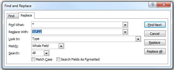
You have been asked to keep the CAD library up to date with MCNs associated with Mfr Part Numbers. You get a Excel report from the PLM system to back annotate the CAD library with MCNs where Mfr Part Number in CAD = Mfr Part Number in PLM.

As shown previously the Mfr P/N for the 16V part is now in the PLM system with two MCNs associated with the same Mfr P/N.  You now have a 50/50 chance of updating CAD library with the correct MCN, that is where the MCN part description will be an exact form, fit and function equivalent to the Mfr P/N.

Back annotating the CAD library with a parameter like Mfr P/N from a PLM system which has 'many to many' relationships could compromise the data integrity in the CAD library.

If the 10V MCN which is now associated with 16V Mfr P/N in PLM is assigned to the 16V Mfr P/N in CAD library then designs which require the 16V part would be compromised.


Conclusion


Careful attention to details are required when assigning MCNs to Mfr Part Numbers in a CAD Library to avoid compromising form, fit and function of the parts defined in PLM.

The specifications of Mfr Part Numbers assigned to a Company Part Number (MCN) must be be equivalent or better than the specifications called for in the MCN.

surrogate key provides the flexibility needed to deal with scenarios, like:
  1. MCNs with one or more Mfr P/Ns
  2. Same Mfr P/Ns used in one or more MCNs
The scenarios described above are frequently found in PLM systems.

To support a product through out it's life cycle requires having alternate Mfr P/Ns which have been qualified and approved for use in the PLM system.

Within a PLM system it is possible to have a Mfr P/N listed under one or more MCNs. 

Using a surrogate key in your CAD Library Database can solve the PLM to CAD Library integration issues created by the many to many relationships that exist in PLM systems.

In Part 3 of this series we take a look at a real world example of the 'many to many' relationship that can exist in a PLM system.

Monday, April 1, 2013

DBLib

An Altium DBLib or SVNDBLib file links your CAD library to a selected data source.

Open the DBLib or SVNDBLib file in Altium.

Select Database Type,  the Parts Backend database is an Access 2007 file.


Then browse and select Parts_Backend.accdb


Select the Table Browser tab at the bottom of the form > Right Click on a record to add or edit parts to the database.

click on image to view


The data source (Parts Access Database in this example) is mapped using a DBLib file.

Both DBLib and SVNDBLib have some very useful options.


Options include enabling which parameters are 'Visible on Add', this applies to new parts placed in the schematic.

Shown below are my preferred settings.

click to view image


Update Values controls which parameters will be modified when using 'Update Parameters From Database'.


Related Links:

Organize Parts
Lifecycle

That's It !

Saturday, March 16, 2013

Tools

Updated Jan 20, 2024


Import Libs
Import Single Part Symbol Libraries.
Related Link: Import Libs

Export Excel 
Export database tables to Excel file types *.xls or *.xlsx.
Related Link: Export Excel

Import Excel
Import Excel data to Parts Tables.
Related Link: Import Excel


MySQL Scripts
Use to generate Parts Scripts for a MySQL Parts Database.
Use with MySQL Workbench to design the Parts schema.

Export MySQL 
Export | pipe delimited | UTF-8 files for Load MySQL

Load MySQL
Fast Load of CSV files for MySQL databases.
Backup Parts
Use to Backup the Parts Database.
Related Link: Backup Parts

Clone Tables
Cloned tables can be used to make offline changes that can be up loaded to MySQL

The Cloned Parts Table is a temporary table which is deleted when
the Parts Frontend is closed or when Config > Apply is selected.

The Cloned Parts table can be exported using Tools > Export.Excel,
The Cloned Parts table can be exported using Tools > Export for MySQL

Clean Parts
Opens the Clean Parts Dialog 

That's It !

PLM - Part 1: One too Many Dilemma

'One too Many Dilemma' is a pun on words for the Relationships' which exist in PLM systems.  

This article attempts to explain the primary integration problem for PLM systems and CAD tools. 

PLM systems support 'many to many' relationships. CAD tools typically have 'one to one' or 'one to many' relationships. 

In the digital computer age numerous PLM, MRP and ERP systems have been created to support the design and manufacturing process. Circuit board EDA and CAD design tools have also advanced considerably during the past decade.

Efforts are being made to integrate PLM systems with PCB design tools with most of the efforts being made in vain. This is due to the 'many to many' relationships which is corner stone feature of PLM systems.

To appreciate the PLM to CAD integration issues, it is necessary to understand the role of the PLM system. PLM systems are designed to support a product through it's life cycle.

In most companies the PLM life cycle for a product begins after the design has been released from engineering to manufacturing.

There is a lot of brainstorming work that occurs in the design phase, such as qualifying parts and optimizing the design for production that is not really useful to put into PLM.

PLM is about maintaining products that are in production and sustaining manufacturing. 

You can find PLM systems that are designed to track your project from conception to the grave. It is just not very efficient to force a design team to use configuration control while a product is in the design phase. 

However if you project is highly critical, say like getting to the moon and back, you may need a complete track record of your project including the design phase work.

PLM systems use Engineering Change Orders (ECOs) to facilitate configuration control during the product's life cycle.

Designs typically begin with a Bill of Materials (BOMs) which list manufacturer part numbers.

PLM systems use Material Control Numbers (MCNs), also known as company part numbers. 

Before a BOM can be released to PLM the MCNs (company part numbers) must be exist in the PLM system.

Manufacturer part numbers are associated with MCNs in PLM systems. 

The approved manufacturer part numbers in PLM are often referred to as the AVL (Approved Vendors List).

Next step is to back-annotate engineering BOM with the MCNs. With MCNs assigned to each line item the BOM is ready to be imported into the PLM system.

In Part 2 we will delve into relationships between the manufacturer part numbers and the MCNs.

PLM - Part 2:  One too Many Dilemma . . .