In most companies the hardware design teams are small consisting of a few electrical engineers and a Librarian / Expert PCB Designer.
Access is a perfect solution for CAD Libraries. Over the years I have worked in big companies and small startups, regardless of the size of the company the PCB design teams were typically small in comparison to the the overall size of the company.
Using a database library can significantly increase the design team's productivity.
Why MS Access is Important
The vast majority of database solutions are simple. As systems tackle larger and larger problems, the number of applications an organization has or can afford decreases.
click on image to view
Source: http://www.fmsinc.com/MicrosoftAccess/Strategy/
Tuesday, January 24, 2017
Microsoft Access - Best Return on Investment
Tuesday, January 3, 2017
Using Altium DBLib to Create Smart Drawings
The Problem:
The hardware design team needed to document several test stations before handing the stations off to manufacturing for production.
Example Test Station (click on images to view)
The task included creating test connection diagrams and bills of materials.
Example Test Station Diagram (Equipment Connections)
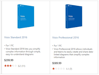
We could have used Microsoft Viso to create the diagrams.
What was needed was an efficient method to create the bills of materials. Creating and maintaining bills of materials (BOMs) from Viso was not an attractive option.
Example Bill of Materials.
We could have asked our mechanical engineer who uses Solidworks to create all the drawings and bills of materials.
Being a small startup we need to use existing tools and resources where possible.
The Solution:
Use Altium and a database library (DBLib) to create Smart Test Diagrams and Bills of Materials.
The bill of materials was created using components (symbols with parametric data).
Component symbols were made using simple lines and arcs. No Pins, Nets or Footprints were needed.
Components were added to the test diagrams to capture parametric data and assign reference designators to the equipment and cables.
The database library (DBlib) was a perfect solution because we only needed to create a few simple symbols to store the parametric data needed to create the BOMs.
Example Component
A component can be created using a simple symbol (short line segment) and the symbol can be linked to parametric data stored in the database library.
Use Component Type - Mechanical (for drawings) to use annotation.
Note: Graphical part types will not be annotated.
One parameter named 'Value' was added to the symbol and made visible to aid in positioning the text in the symbol.
The comment could be used instead of the Value field, however I prefer to use the symbol's comment parameter for other purposes.
A close look at W4 using the simple component (line segment).
If desired the line segment can be hidden behind another object using:
Edit > Move > Send to Back > Select the line segment.
Smart PDF - Test Diagrams
Smart PDFs can display parametric data and they can include hyperlinks.
Summary:
Using Altium's schematic editor and a DBLib Library we created Smart Test Diagrams and Bills of Materials.
That's it !
The hardware design team needed to document several test stations before handing the stations off to manufacturing for production.
Example Test Station (click on images to view)
The task included creating test connection diagrams and bills of materials.
Example Test Station Diagram (Equipment Connections)
What was needed was an efficient method to create the bills of materials. Creating and maintaining bills of materials (BOMs) from Viso was not an attractive option.
Example Bill of Materials.
We could have asked our mechanical engineer who uses Solidworks to create all the drawings and bills of materials.
Being a small startup we need to use existing tools and resources where possible.
The Solution:
Use Altium and a database library (DBLib) to create Smart Test Diagrams and Bills of Materials.
The bill of materials was created using components (symbols with parametric data).
Component symbols were made using simple lines and arcs. No Pins, Nets or Footprints were needed.
Components were added to the test diagrams to capture parametric data and assign reference designators to the equipment and cables.
The database library (DBlib) was a perfect solution because we only needed to create a few simple symbols to store the parametric data needed to create the BOMs.
Example Component
A component can be created using a simple symbol (short line segment) and the symbol can be linked to parametric data stored in the database library.
Use Component Type - Mechanical (for drawings) to use annotation.
Note: Graphical part types will not be annotated.
One parameter named 'Value' was added to the symbol and made visible to aid in positioning the text in the symbol.
The comment could be used instead of the Value field, however I prefer to use the symbol's comment parameter for other purposes.
A close look at W4 using the simple component (line segment).
If desired the line segment can be hidden behind another object using:
Edit > Move > Send to Back > Select the line segment.
Smart PDF - Test Diagrams
Summary:
Using Altium's schematic editor and a DBLib Library we created Smart Test Diagrams and Bills of Materials.
That's it !
Subscribe to:
Posts (Atom)